- 您现在的位置:买卖IC网 > Sheet目录323 > DV164122 (Microchip Technology)ANALYZER SRL PICKIT W/DEMO BOARD
PICkit? Serial Analyzer User’s Guide
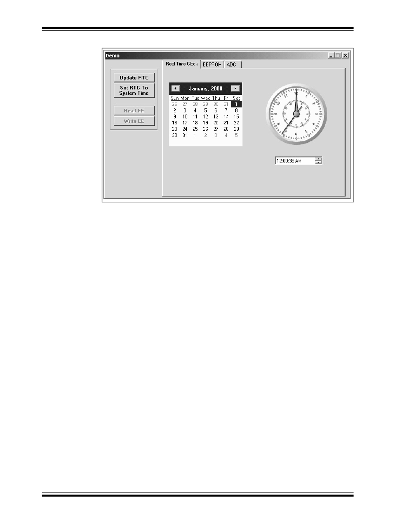
FIGURE 2-3:
28-PIN DEMO I 2 C? – RTC
2.7.2
Serial EEPROM (EEPROM)
Clicking on the EEPROM tab will display the 256 byte array of EEPROM memory as
shown in Figure 2-4. The 28-Pin Demo Board has been programmed to emulate a
stand-alone serial I 2 C EEPROM device such as a 24LC02. The I 2 C commands are
very similar to the commands used in these devices.
The Serial EEPROM tab displays the contents of a serial EEPROM implemented on
the 28-Pin Demo Board. When this tab is first displayed, the values are grayed out. This
means that the display does not match the contents of the emulated serial EEPROM.
Click on Read EE button and the program will read and display the contents of the
28-Pin Demo Board. Notice that the displayed values are now black.
Individual memory locations can be changed by clicking on the value and typing in a
new value in hexadecimal. Notice that the changed values will be displayed in red. This
means the value has changed but has not been written to the emulated serial
EEPROM. Click on the Write EE button and the values will be written. The color of the
value will turn to black indicating that the value has been written and the display
matches the contents of the emulated serial EEPROM.
DS51647A-page 12
? 2007 Microchip Technology Inc.
发布紧急采购,3分钟左右您将得到回复。
相关PDF资料
DV164131
KIT STARTER PICKIT 3
DV164132
KIT EVAL F1 FOR PIC12F1/PIC16F1
DV243003
KIT STARTER FOR SRL MEM PRODUCTS
DVA1001
ADAPTER FOR PIC16F716 18DIP
DVA1004
DEVICE ADAPTER 8/14/20DIP
E3R-D12GP-P
RELAY RCVR PLUG-IN DIMMER
E3R-R12-3HOTP
RCVR 3WIRE RELAY 120V
E3R-R12GP
RCVR PLUG-IN RELAY
相关代理商/技术参数
DV164126
功能描述:开发板和工具包 - PIC / DSPIC USB Kit w/ PICkit LowPinCount RoHS:否 制造商:Microchip Technology 产品:Starter Kits 工具用于评估:chipKIT 核心:Uno32 接口类型: 工作电源电压:
DV164130
功能描述:电路内置调试器 PICkit 3 Starter Kit
RoHS:否 制造商:Microchip Technology 产品:In-Circuit Debugger Kits 工具用于评估:PIC16F1829 用于:PIC16F1829 核心:PIC 接口类型: 工作电源电压:
DV164131
功能描述:电路内置调试器 PICkit 3 Debug Exprs RoHS:否 制造商:Microchip Technology 产品:In-Circuit Debugger Kits 工具用于评估:PIC MCUs, dsPIC DSCs 用于:07-00024, AC164113 核心:dsPIC, PIC 接口类型:USB 工作电源电压:3 V to 5 V
DV164131
制造商:Microchip Technology Inc 功能描述:PICKIT 3 DEBUG EXPRESS
DV164131-XLP
制造商:Microchip Technology Inc 功能描述:KIT DEV PICKIT 3-XLP/NANOWAT
DV164132
功能描述:开发板和工具包 - PIC / DSPIC F1 Evaluation Kit RoHS:否 制造商:Microchip Technology 产品:Starter Kits 工具用于评估:chipKIT 核心:Uno32 接口类型: 工作电源电压:
DV164132
制造商:Microchip Technology Inc 功能描述:PIC12F1xxx/PIC16F1xxx F1 Evaluation Kit
DV164133
功能描述:电源管理IC开发工具 Energy Harvesting Development Tool
RoHS:否 制造商:Maxim Integrated 产品:Evaluation Kits 类型:Battery Management 工具用于评估:MAX17710GB 输入电压: 输出电压:1.8 V
